Electrical Schematics
How do the component values, wires and junctions survive?
✅ NormativeSettled. The requirement holds as written.📄 Page ruleCan be applied from the page alone.Read §12.2.3 in the RFC ↗
A component-level circuit schematic MUST use a faithful diagram/<language> encoding,
preferring diagram/circuitikz, then diagram/tikz, then diagram/svg. If no suitable language
can faithfully represent it, it MUST use a fenced description block. Every component symbol,
designator, value, pin, terminal, net label and visibly drawn connection MUST be preserved.
When it applies
Circuit diagrams.
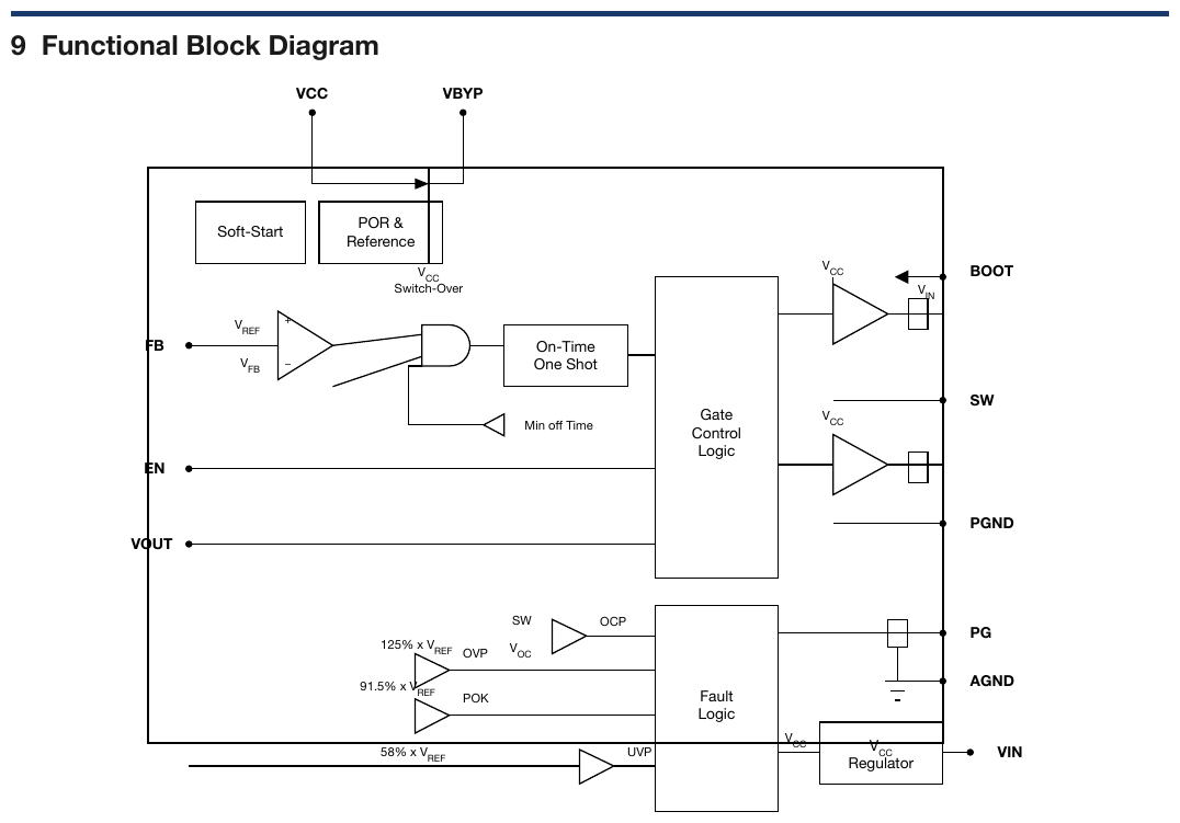
The figure above is an IC functional block diagram rather than a component-level circuit; it follows
Diagrams and Flowcharts (§12.2.2), using diagram/plantUml, diagram/mermaid or another suitable language
that preserves the printed blocks and signal connections. The component-level requirements below
do not apply to a functional block diagram.
Reading the examples. Each one pairs a source page with the output the rule expects. ✅ Sample: the rule applies. ❌ Counter-sample: it looks like it applies and does not, or a rendering got it wrong. A non-conforming output, in red, is shown only for contrast. … marks content left out of an excerpt.
The point, in a small example
Start with a real component circuit, then compare the same crossing with and without a junction dot. Each expected encoding is compilable CircuiTikZ. These pages are made up to isolate the rule.
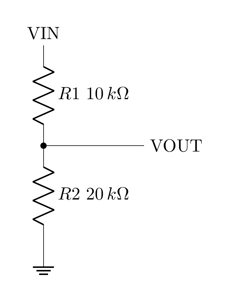
A resistor divider preserves the branch and values
This is a component-level circuit, not a process flow. Preserve R1, R2, their printed values, the ground symbol and the VOUT branch at the marked junction. Do not calculate an unprinted output voltage.
Source page
Expected output
```diagram/circuitikz
\begin{circuitikz}[american]
\draw (0,4) node[above]{VIN} to[R,l=$R1\ 10\,k\Omega$] (0,2)
  to[R,l=$R2\ 20\,k\Omega$] (0,0) node[ground]{};
\draw (0,2) node[circ]{} -- (2,2) node[right]{VOUT};
\end{circuitikz}
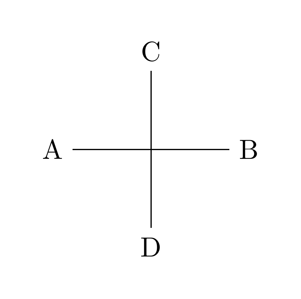
```Crossing wires are not automatically connected
Compare with the other crossing example: there is no junction marker. Preserve the two crossing wires without asserting an electrical connection at their crossing. Do not infer hidden connections from proximity.
Source page
Expected output
```diagram/circuitikz
\begin{circuitikz}
\draw (0,1) node[left]{A} -- (2,1) node[right]{B};
\draw (1,0) node[below]{D} -- (1,2) node[above]{C};

\end{circuitikz}
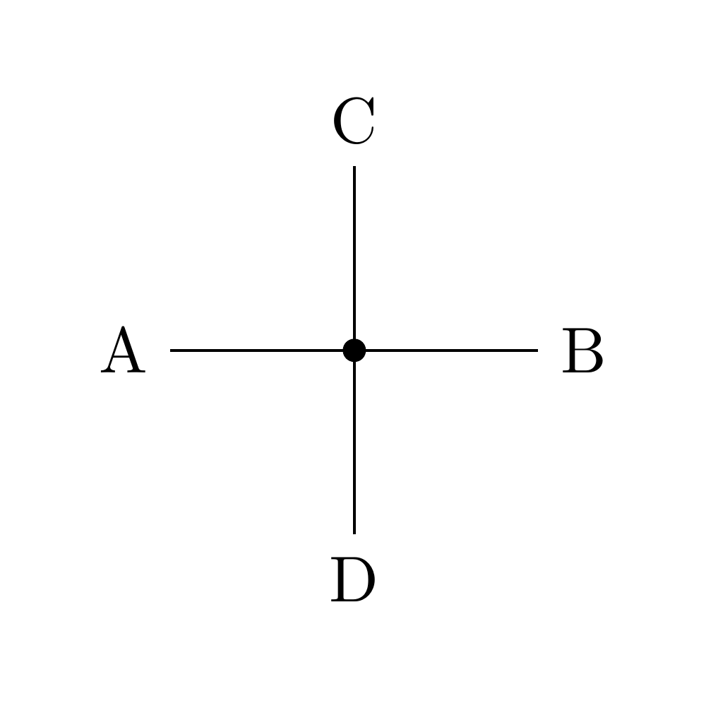
```The junction dot changes connectivity
Compare with the other crossing example: the visible dot joins all four labeled ends. Do not infer hidden connections from proximity.
Source page
Expected output
```diagram/circuitikz
\begin{circuitikz}
\draw (0,1) node[left]{A} -- (2,1) node[right]{B};
\draw (1,0) node[below]{D} -- (1,2) node[above]{C};
\node[circ] at (1,1) {};
\end{circuitikz}
```How the element is recognised
Component symbols joined by wires, usually with a reference designator and a value beside each one
(R1 1Ω, C3 10μF). The way the components are oriented, and whether they sit in series or in
parallel, is part of the content.
Preserve circuit meaning
The encoding MUST preserve component orientation, pins, junctions, crossings and series/parallel connections as drawn. An automatic graph layout that changes circuit meaning MUST NOT be used. Functional block diagrams use the block-diagram priorities in Diagrams and Flowcharts (§12.2.2).
The fixed shape
When no suitable language can faithfully encode the circuit, the fallback uses a fenced
description block (see
Slide Diagrams (§12.2.5)).
- What it is — one line:
Buck regulator input stage. - Components — a list, one item per component in reading order (top to bottom, left to
right): designator then value, both exactly as printed (
R1 1Ω,C3 10μF). A component with no printed value is listed by its designator. - Pins, terminals and nets — every printed pin, terminal and net label, verbatim.
- Connections — describe wires and junctions visibly drawn between identified parts. A crossing MUST NOT be treated as a junction unless the drawing marks it as one. Hidden or ambiguous connections MUST NOT be guessed.
Every printed designator, value and label is printed content and MUST be transcribed (never drop). Values MUST NOT be computed, normalised or corrected.
Neighbouring rules, and how they differ
More
Rule id diagrams-electrical-schematics · images diagrams