Blueprints
How do walls, doorways and dimensions survive the encoding?
✅ NormativeSettled. The requirement holds as written.📄 Page ruleCan be applied from the page alone.Read §12.2.1 in the RFC ↗
A floor plan or architectural drawing MUST use a faithful diagram/<language> encoding,
preferring diagram/tikz then diagram/svg. If no suitable language can represent it faithfully,
it MUST use a fenced description block. The output MUST preserve visible geometry, labels and
printed measurements without inferred relationships or computed values. It MUST NOT be a table.
When it applies
Floor plans and architectural drawings.
Reading the examples. Each one pairs a source page with the output the rule expects. ✅ Sample: the rule applies. ❌ Counter-sample: it looks like it applies and does not, or a rendering got it wrong. A non-conforming output, in red, is shown only for contrast. … marks content left out of an excerpt.
The point, in a small example
The first example demonstrates the preferred faithful encoding. The RFC’s larger plan remains below as its explicitly conditional description-fallback example; complexity alone does not justify choosing that fallback. These pages are made up to isolate the rule; the RFC’s real-document examples follow under each part of the rule.
A floor plan retains the doorway and printed dimensions
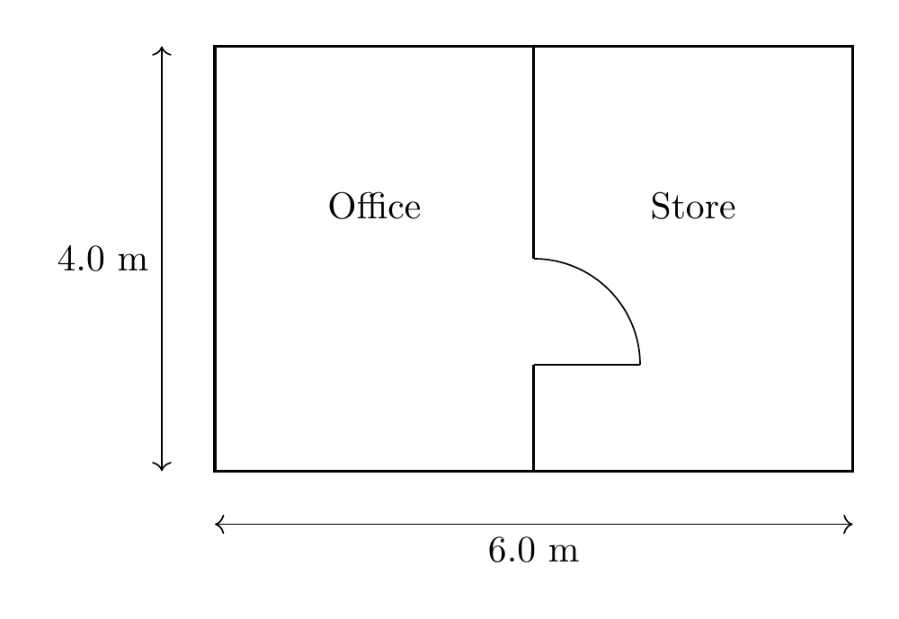
The internal wall has a visible opening and a door swing into Store. Keep both room labels and the two printed overall dimensions. Drawing coordinates reproduce the schematic; they do not authorize invented room dimensions or calculated areas. This simple plan has a faithful encoding, so a description fallback is unnecessary.
Source page
Expected output
```diagram/tikz
\begin{tikzpicture}[x=1cm,y=1cm]
\draw[thick] (0,0) rectangle (6,4);
\draw[thick] (3,0) -- (3,1) (3,2) -- (3,4);
\draw (3,1) -- (4,1);
\draw (4,1) arc[start angle=0,end angle=90,radius=1];
\node at (1.5,2.5) {Office};
\node at (4.5,2.5) {Store};
\draw[<->] (0,-0.5) -- (6,-0.5) node[midway,below]{6.0 m};
\draw[<->] (-0.5,0) -- (-0.5,4) node[midway,left]{4.0 m};
\end{tikzpicture}
```How the element is recognised
A drawing whose content is spatial: walls, rooms, dimensions, door swings, labels placed where the thing they name sits. There are no rows and no columns — only positions.
Why a table is the wrong answer
A floor plan forced into a grid becomes a table of spatially adjacent labels that reads as data downstream. That is worse than a description, because it is confidently wrong: nothing in the output signals that the rows and columns were invented — the never invent failure. A floor plan MUST NOT be rendered as a table.
The same trap appears in Geographic Maps (§12.2.4) (map coerced into a table) and Electrical Schematics (§12.2.3) (circuit coerced into a graph): a spatial artefact flattened into a linear structure that cannot carry position.
Encode the spatial content
Language selection follows Diagrams and Flowcharts (§12.2.2). The encoding MUST preserve visible walls, openings, door swings, relative positions, dimensions, labels, scale bars, legends and notes. Drawing coordinates MAY follow the visible geometry; they MUST NOT assert unprinted real-world measurements. Inconsistent printed dimensions MUST be copied without correction. A room graph that drops geometry is not a faithful encoding of a floor plan.
Description fallback
Only when no suitable language can faithfully encode the drawing, use a fenced description
block in this shape:
- What it is — one line describing the drawing.
- Areas and visible structure — one item per labelled area in reading order, its printed label and size verbatim, followed by visible walls, openings and spatial relationships.
- Dimensions and notes — every dimension line, scale bar, legend entry, north arrow label and note, verbatim.
Unshown adjacency, hidden openings, computed areas and corrected dimensions MUST NOT be added. A visible doorway or shared wall may be described as drawn; proximity alone does not establish a connection. The description MUST distinguish what is visible from what cannot be determined.
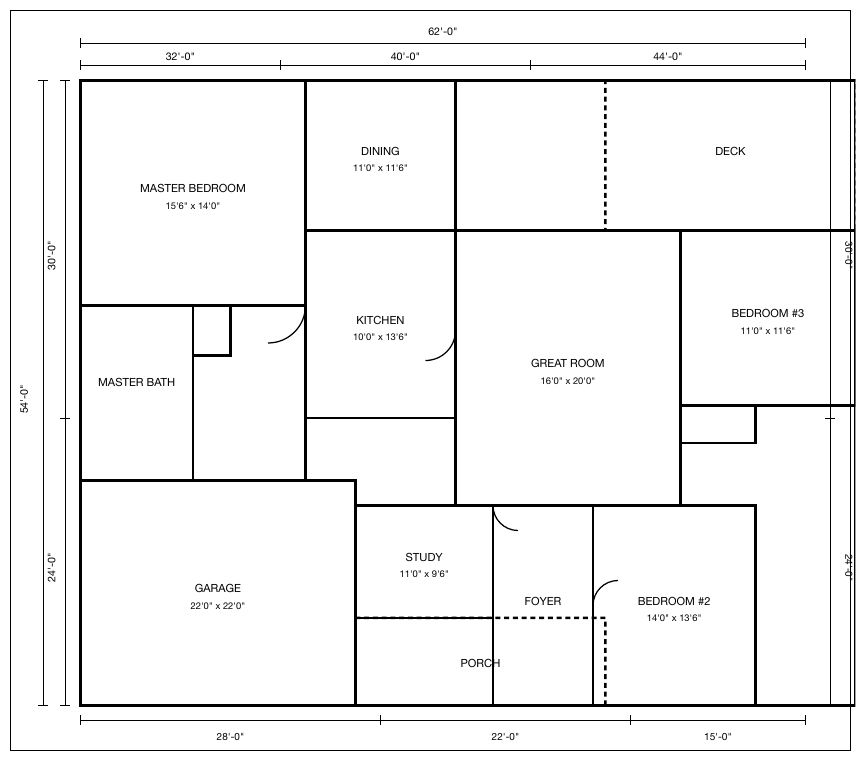
a single-storey plan
Twelve labelled areas, eight of them with a printed size, and dimension lines on all four sides. The
printed dimensions do not add up (32'-0", 40'-0" and 44'-0" under a 62'-0" span) and are
copied as printed.
Source page
Expected output · description fallback when no faithful encoding is available
Floor plan of a single-storey house.
- MASTER BEDROOM 15'6" x 14'0"
- DINING 11'0" x 11'6"
- DECK
- KITCHEN 10'0" x 13'6"
- GREAT ROOM 16'0" x 20'0"
- BEDROOM #3 11'0" x 11'6"
- MASTER BATH
- GARAGE 22'0" x 22'0"
- STUDY 11'0" x 9'6"
- FOYER
- BEDROOM #2 14'0" x 13'6"
- PORCH
Dimension lines: 62'-0" across the top, divided 32'-0", 40'-0", 44'-0"; 28'-0", 22'-0", 15'-0" along the bottom; 54'-0" down the left, divided 30'-0", 24'-0"; 30'-0" and 24'-0" on the right.
More
Rule id diagrams-blueprints · images diagrams